
Specifications
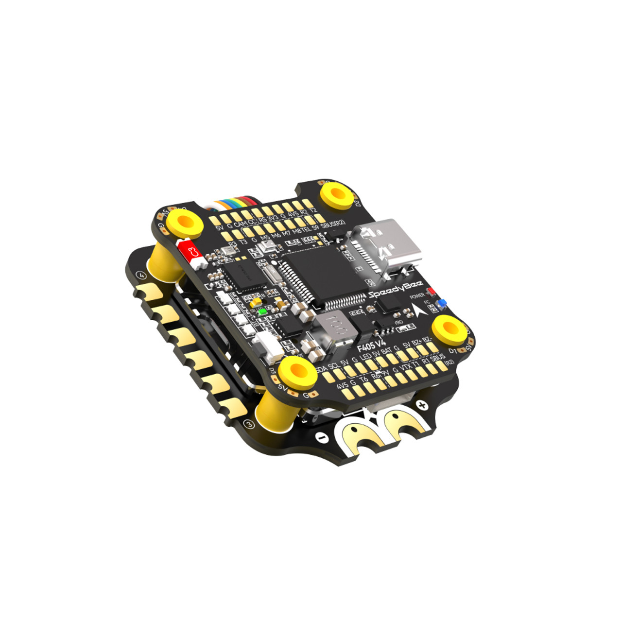
| Product Name | SpeedyBee F405 V3 30×30 Flight Controller |
| MCU | STM32F405 |
| IMU(Gyro) | BMI270 |
| USB Port Type | Type-C |
| Barometer | Built-in |
| OSD Chip | AT7456E chip |
| BLE Bluetooth | Supported. Used for Flight Controller configuration |
| DJI Air Unit Connection Way | Two ways supported: 6-pin connector or direct soldering. |
| Blackbox MicroSD Card Slot | *Betaflight firmware requires the type of the microSD card to be either Standard (SDSC) or High capacity (SDHC), so extended capacity cards (SDXC) are not supported(Many high-speed U3 cards are SDXC). Also the card MUST be formatted with the FAT16 or FAT32 (recommended) filesystems. So, you could use any SD card less than 32GB, but the Betaflight can only recognize 4GB maximum. We suggest you use this 3rd party formatting tool and choose ‘Overwrite format’ then format your card. Also check out here for the recommended SD cards or buy the tested cards from our store. |
| BetaFlight Camera Control Pad | Yes(CC pad on the front side) |
| Current Sensor Input | Supported. For SpeedyBee BLS 50A ESC, please set scale = 386 and Offset = 0. |
| Power Input | 3S – 6S Lipo(Through G, BAT pins/pads from the 8-pin connector or 8-pads on the bottom side) |
| 5V Output | 9 groups of 5V output, four +5V pads and 1 BZ+ pad( used for Buzzer) on front side, and 4x LED 5V pads. The total current load is 2A. |
| 9V Output | 2 groups of 9V output, one +9V pad on front side and other included in a connector on bottom side. The total current load is 2A. |
| 3.3V Output | Supported. Designed for 3.3V-input receivers. Up to 500mA current load. |
| 4.5V Output | Supported. Designed for receiver and GPS module even when the FC is powered through the USB port. Up to 1A current load. |
| ESC Signal | M1 – M4 on bottom side and M5-M8 on front side. |
| UART | 5 sets(UART1, UART2, UART3, UART4(For ESC Telemetry), UART6) |
| ESC Telemetry UART | R4(UART4) |
| I2C | Supported. SDA & SCL pads on front side. Used for magnetometer, sonar, etc. |
| Traditional Betaflight LED Pad | Supported. 5V, G and LED pads on bottom of the front side. Used for WS2812 LED controlled by Betaflight firmware. |
| Buzzer | BZ+ and BZ- pad used for 5V Buzzer |
| BOOT Button | Supported. [A]. Press and hold BOOT button and power the FC on at the same time will force the FC to enter DFU mode, this is for firmware flashing when the FC gets bricked. [B]. When the FC is powered on and in standby mode, the BOOT button can be used to controller the LED strips connected to LED1-LED4 connectors on the bottom side. By default, short-press the BOOT button to cycle the LED displaying mode. Long-press the BOOT button to switch between SpeedyBee-LED mode and BF-LED mode. Under BF-LED mode, all the LED1-LED4 strips will be controlled by Betaflight firmware. |
| RSSI Input | Supported. Named as RS on the front side. |
| SmartPort | Use any TX pad of UART for the SmartPort feature. |
| Supported Flight Controller Firmware | BetaFlight(Default), EMUFlight, INAV |
| Firmware Target Name | SPEEDYBEEF405V3 |
| Mounting | 30.5 x 30.5mm( 4mm hole diameter) |
| Dimension | 41.6(L) x 39.4(W) x 7.8(H)mm |
| Weight | 9.6g |
| Product Name | SpeedyBee BLS 50A 30×30 4-in-1 ESC |
| Firmware | BLHeli_S JH50 |
| Wireless Configuration | Full Configuration Supported in the SpeedyBee app |
| PC Configurator Download Link | https://esc-configurator.com/ |
| Continuous Current | 50A * 4 |
| Burst Current | 55A(5S) |
| TVS Protective diode | Yes |
| External Capacitor | 1500uF Low ESR Capacitor(In the package) |
| ESC Protocol | DSHOT300/600 |
| Power Input | 3-6S LiPo |
| Power Output | VBAT |
| Current Sensor | Support (Scale=386 Offset=0) |
| Mounting | 30.5 x 30.5mm( 4mm hole diameter) |
| Dimension | 45.6(L) * 44(W) * 6.1mm(H) |
| Weight | 13.8g |


Reviews
There are no reviews yet.